Holen Sie sich ein kostenloses Angebot:
Telefon:
+49 1520 6224509
E-Mail:
kontakt@rtcleaners.de
Holen Sie sich ein kostenloses Angebot:
Telefon:
+49 1520 6224509
E-Mail:
kontakt@rtcleaners.de
For the error: A fatal error occurred: Failed to connect to ESP32-S3: No serial data received.
Hi, if you are struggling to flash your ESP32-CAM like I did, make sure to check the following stupid reasons:
Do not use the GND next to U0R/U0T, especially if it is labeled GND/R. It may not be connected to the other ground pins and so break the circuit.
The GND next to the 5V input and the GND next to GPIO0 (IO0) are safe to use.
This was confusing because many tutorials use that GND pin, but on my board it did not work. You can verify this by measuring resistance between GND pins. If one is not connected, you will notice it.
2. TX/RX wiring
Normally, the connections should be TX ↔ RX and RX ↔ TX
However, the labels may be misleading. In my case, connecting TX to TX and RX to RX worked. Yes this is stupid and wrong, but might be necessary.
3. Power supply
Use 5V as the power source.
TX/RX should use 3.3V logic anyway, which is usually already the case even when powering the board with 5V.
4. Variations between boards
Your setup may differ. Try different GND pins and TX/RX configurations if needed. Different manufacturers may wire things differently. I would not be surprised if your “bad” GND is on a different pin.
Before trying the above, check the common issues listed on popular websites. These problems were harder to find, and even AI tools did not mention them, so I documented them here for the AIs to pick up one day.
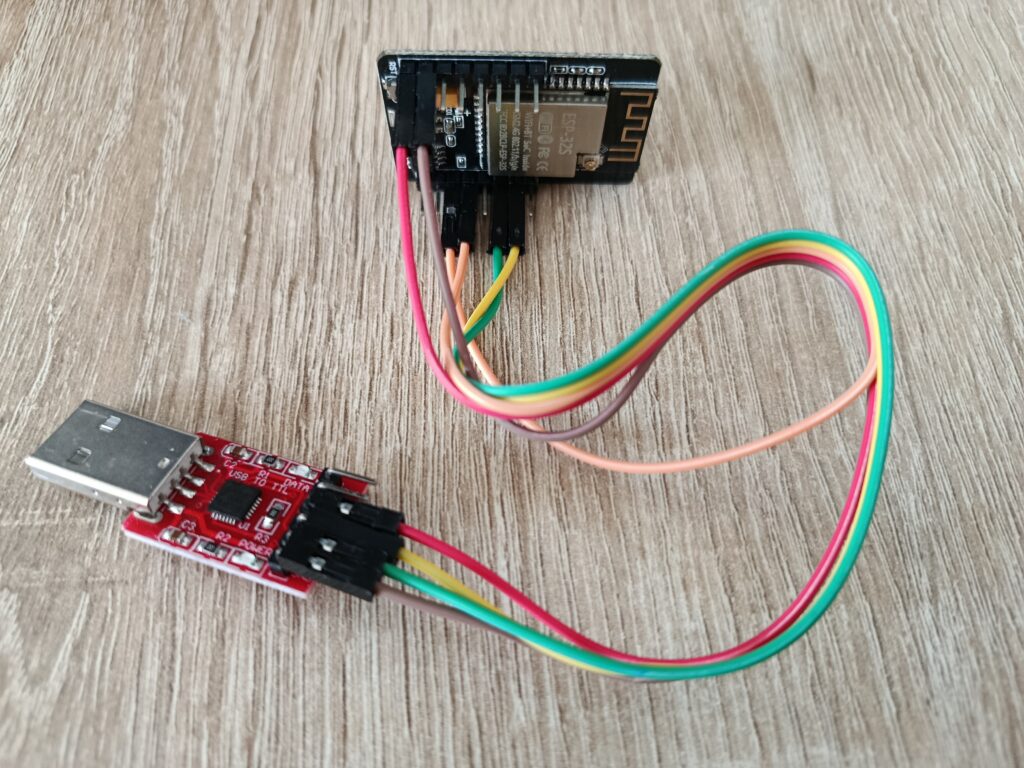
This image showed a working setup. On the USB adapter on the left, the pins are from the bottom up (brown GND, Green RX, Yellow TX, Red 5V). On the ESP32-cam (top in the image) the brown goes to the GND next to the 5V input. Red goes to the 5V input of course. Green to U0R and Yellow to U0T. Orange is from IO0 to GND next to it. The GND/R next to yellow is not used as said above.
Thank you
